What is an Inductor?
An inductor is a passive electronic component that stores energy in a magnetic field when electrical current flows through it. Think of it as a coil of wire that resists changes in current.
Unlike capacitors that store energy in an electric field, inductors store energy in a magnetic field. This makes them essential for filtering, energy storage, and voltage conversion in power supplies.
Inductors are found in nearly every electronic device - power supplies, DC-DC converters, filters, radios, and motherboards.
How to Identify an Inductor
Visual Characteristics:
- Shape: Usually a coil of wire, often with a ferrite core
- Colors: Can be bare copper, colored ring, or black epoxy coated
- Markings: Often have a colored band or printed value (e.g., 100, 101, 220)
- Types: Drum core, toroidal, chip inductor, or axial leaded
Common Inductor Types You'll See:
Drum Core Inductors (most common)
- Small cylinder shape with wire wrapped around
- Often found on motherboards and power supplies
- Usually black or gray with a flat top
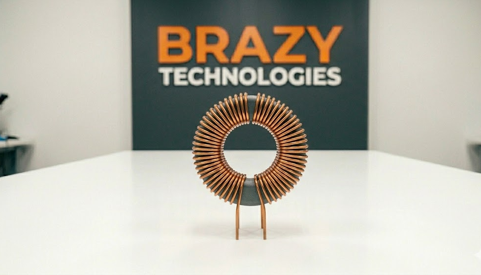
Toroidal Inductors
- Donut-shaped ring with wire wrapped around entire core
- Found in high-end power supplies and audio equipment
- Very efficient but larger in size
Chip Inductors (surface mount)
- Tiny black rectangle with silver ends
- Look similar to capacitors but usually have markings
- Found on phones, tablets, and modern electronics
Axial Inductors (older style)
- Cylindrical with wire leads coming out each end
- Color bands similar to resistors
- Found in older electronics and some power supplies
What Do Inductors Do?
Inductors have three main jobs in circuits:
1. Filtering
They smooth out electrical noise and ripple in power supplies. Combined with capacitors, they create LC filters that clean up dirty power.
2. Energy Storage
In switching power supplies and DC-DC converters, inductors store and release energy to change voltage levels (buck converters step down, boost converters step up).
3. Blocking AC
Inductors resist changes in current. They pass DC easily but block high-frequency AC. This property is used in radio frequency circuits and filters.
Common Equipment Where Inductors Fail
Inductors are generally reliable, but they can fail from:
- Physical damage (dropped devices)
- Overheating (too much current)
- Age and thermal stress
- Manufacturing defects
Where you'll find them:
- Power supplies (computer PSUs, laptop chargers)
- DC-DC converters (voltage regulator modules on motherboards)
- LCD monitor power boards
- Audio amplifiers (crossover networks)
- Radio frequency circuits
- LED drivers
- Automotive electronics
Signs of a Bad Inductor
Visible Signs:
- Cracked or broken core (ceramic or ferrite material cracked)
- Burned or discolored epoxy coating
- Melted plastic casing
- Loose or broken wire leads
- Burnt circuit board underneath (darkened area)
Invisible Signs (Need Testing):
- Device powers on but has excessive noise or whine
- Voltage output is incorrect or unstable
- Device works intermittently
- Excessive heat from the inductor area
- Circuit draws too much current
The #1 Sign: A physically cracked inductor core is always bad. Replace it immediately.
How to Test an Inductor with a Multimeter
Testing inductors is straightforward but requires the right approach.
What You Need:
- Digital multimeter with resistance (Ohms) mode
- Some multimeters have inductance (H) mode - very helpful
- Optional: LCR meter for precise testing
Method 1: Resistance Test (Quick Check)
Step 1: Power off and unplug the device
Step 2: Set multimeter to resistance (Ohms) mode, lowest range (200 Ohms)
Step 3: Place probes on each lead of the inductor
What the reading means:
- Low resistance (near 0 Ohms) = Good inductor (wire is intact)
- Infinite resistance (OL) = Bad inductor (open circuit)
- Very high resistance (100+ Ohms) = Suspicious - may be damaged
Important: Inductors are just coils of wire. A good inductor should read almost zero Ohms (dead short). If it reads open, the wire is broken inside.
Method 2: Inductance Test (More Accurate)
If your multimeter has inductance (H) mode:
1. Set multimeter to inductance mode (look for "H" symbol)
2. Place probes on inductor leads
3. Compare reading to labeled value
A good inductor should read within 10-20% of its rated value.
Common Inductor Values and Markings
Inductors use several marking systems:
Standard Values (microhenries - uH)
1.0, 1.2, 1.5, 1.8, 2.2, 2.7, 3.3, 3.9, 4.7, 5.6, 6.8, 8.2, 10, 12, 15, 18, 22, 27, 33, 39, 47, 56, 68, 82, 100, 120, 150, 180, 220, 270, 330, 390, 470, 560, 680, 820, 1000
Code Markings (similar to capacitors):
- 101 = 100 uH (10 + 1 zero)
- 220 = 22 uH (22 + 0 zeros)
- 471 = 470 uH (47 + 1 zero)
- 102 = 1000 uH (10 + 2 zeros)
Color Bands (axial inductors):
Same as resistor color code but the value is in microhenries (uH)
Example: Brown - Black - Red = 10 with 2 zeros = 1000 uH
Why Inductors Fail
Physical Damage (most common)
- Dropped devices crack the ferrite core
- Cracked cores change inductance value drastically
- Visible cracks mean immediate replacement
Overheating
- Too much current melts the wire insulation
- Adjacent hot components can damage inductors
- Look for melted plastic or darkened board
Soldering Damage
- Excessive heat during soldering can damage internal connections
- Use proper temperature (under 400°C / 750°F)
Age
- Thermal cycles weaken wire connections over time
- More common in power supplies run 24/7
How to Replace a Bad Inductor
Tools Needed:
- Soldering iron (temperature controlled)
- Desoldering pump or wick
- Replacement inductor (exact value AND type)
- Tweezers (for surface mount inductors)
Step-by-Step Replacement:
Through-Hole Inductor:
1. Note orientation (most are not polarized - any direction works)
2. Heat one solder joint while pulling gently on that lead
3. Heat the other joint and pull the inductor free
4. Clean pads with desoldering wick
5. Insert new inductor (orientation doesn't matter for most)
6. Solder both leads
7. Clip excess leads
Surface Mount Inductor:
1. Apply flux to both solder pads
2. Heat one pad with soldering iron
3. Slide inductor off while solder is molten (use tweezers)
4. Clean pads with desoldering wick
5. Place new inductor on pads (align carefully)
6. Heat one pad to tack it in place
7. Solder the other pad
8. Re-solder first pad for a good joint
Pro Technician Tips
Tip 1: When replacing an inductor, match the value EXACTLY. Inductance value is critical for circuit operation.
Tip 2: Physical size matters. Use the same size replacement (especially for power inductors). A smaller inductor may overheat.
Tip 3: If an inductor burned open, something else caused it. Check for shorted MOSFETs or capacitors nearby.
Tip 4: For surface mount inductors, avoid excessive heat. Use low temperature (320-350°C) and work quickly.
Tip 5: Some inductors are shielded (solid plastic casing) and some are unshielded (visible wire coils). Either works for replacement as long as physical size fits.
Tip 6: When testing in-circuit, other components can affect readings. If you get a strange reading, lift one leg and test again.
Quick Troubleshooting Guide
Symptom: Inductor reads infinite resistance (OL)
- Diagnosis: Open circuit - wire broken inside
- Action: Replace immediately
Symptom: Inductor reads very low resistance (0.1-2 Ohms)
- Diagnosis: Normal for most power inductors
- Action: Likely good, check other components
Symptom: Inductor reads higher than expected resistance
- Diagnosis: Partial open - damaged but still conducting
- Action: Replace - unreliable
Symptom: Cracked or broken core
- Diagnosis: Physically damaged
- Action: Replace - inductance value changed
Symptom: Burnt or melted casing
- Diagnosis: Overheated from excess current
- Action: Replace AND find what caused the overcurrent
Practice Exercise
Find an old computer power supply or broken motherboard:
1. Locate all inductors (look for small cylinders with wire)
2. Identify the different types (drum core, toroidal, chip)
3. Test each with your multimeter in resistance mode
4. Compare readings - most should be near zero Ohms
5. Look for any cracked or burnt inductors
After practicing on 10-20 boards, you'll quickly spot bad inductors by sight and testing.
Summary: Key Takeaways
- Inductors store energy in a magnetic field
- They look like coils of wire, often on a ferrite core
- Good inductors read near zero Ohms (dead short)
- Bad inductors read open (infinite resistance)
- Cracked core = replace immediately
- Always match value and physical size when replacing
- If an inductor burned, find the root cause first
Now you know how to identify, test, and replace inductors - essential skills for power supply and motherboard repair!
Want to master advanced component-level repair?
The full masterclass covers:
- Understanding buck and boost converters
- Professional power supply troubleshooting
Join the waitlist for early access and certification program.